Resistance welding with direct current (DC) using inverter technology (MFDC) reduces costs by improving quality, reducing maintenance, and increasing productivity.
Switching from traditional alternative current (AC) to DC with inverters also reduces a range of facilities costs and improves the process. Finally, it provides the ability to weld new materials, so it can add to a company's capability or product scope.
TRANSISTOR DIRECT CURRENT (LINEAR DC) WELDING
Specific high precision micro welding - Very thin plate welding
The transistor direct current power supplies (also called “Linear DC”) produce much the same results as the high frequency inverter by using a high number of power transistors as the direct energy source. This technology provides clean, square wave forms with extremely fast rise time. Used primarily in constant voltage feedback control, transistor DC power supplies are effective in thin foils and fine wire welding applications and for extremely short welds.
Linear DC welders utilize transistor controlled feedback enabling total feedback response times of less than 5 µS. The term Linear DC comes from the waveform that is output from the power supply. No transformer is utilized. The primary limitation to Linear DC technology is the low duty cycles, typically much less than 1 weld per second at less than rated output.
Typically, constant voltage feedback is utilized in conjunction with short weld pulses. Because the feedback response is so rapid, high energy welds with extremely short duration can be used without weld splash or arcing. These short pulses limit the heat stress and the size of the heat affected zone on the weldments. This provides a stronger more ductile weld joint, along with less part deformation, less discoloration, and significantly longer electrode life.
Constant voltage feedback is chosen for two reasons: its ability to prevent arcing and to provide the optimum weld power distribution based on the part resistance. If for some reason the weldments collapse faster than the weld head can follow up, arcing usually occurs. When constant voltage feedback is applied with the feedback response times capable by Linear DC welding this arcing is minimized.
Transistor DC units tend to be larger and heavier than other resistance welding power supply technologies.
MEDIUM FREQUENCY (MFDC) INVERTER WELDING
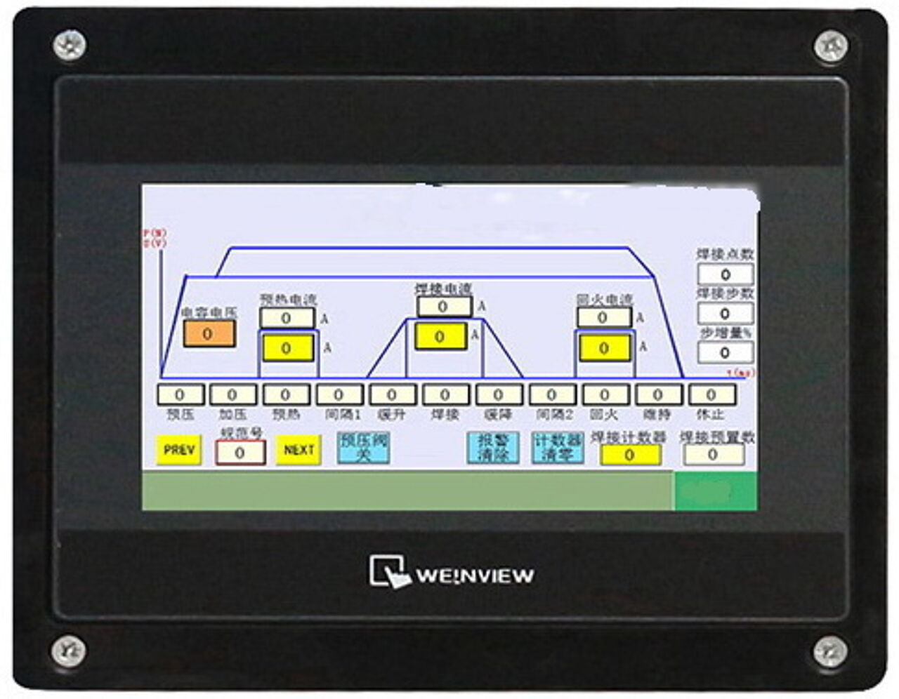
Digital Medium Frequency (MFDC) Inverter welding Controller
Three Phase Inverter DC utilizes three-phase balanced input. Current is in full wave form rectified to DC and switch to 1000Hz or higher to produce AC supply to primary transformer. The current is rectified into DC for welding afterwards.
Medium (till 1000Hz) Frequency Inverter Welders use millisecond pulse width modulation (switching) technology with closed-loop feedback to control the weld energy in sub-millisecond increments. Three phase input current is full wave rectified to DC and switched at 1kHz to produce an AC current at the primary of the welding transformer. The secondary current is then rectified to produce DC welding current with an imposed, low-level, AC ripple. The high-speed feedback circuitry enables the inverter power supply to adapt to changes in the secondary loop resistance and the dynamics of the welding process. For example, a 1 kHz inverter power supply adjusts the output current every 0.5 miliseconds after rectification, which also allows the weld time (duration of current) to be controlled accurately in increments as small as 1 milliseconds. The high frequency closed loop feedback can be used to control (maintain constant) either current, voltage, or power while also monitoring another of the same three parameters.
Additional benefits of high frequency switching technology include reduced power consumption, smaller welding transformers, and the use of a very short pre-weld “check pulse” to test electrode and parts positioning prior to executing a weld. The result of this pre-weld check can be used to inhibit the weld by setting check limits.
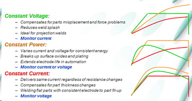
CONSTANT CURRENT can be used for 65% of all welding applications including those that exhibit low contact resistance, small variability in contact resistance, flat parts, and multiple part “sandwiches.”
CONSTANT VOLTAGE can be used for applications where the workpieces do not have flat surfaces, e.g. crossed wires, and where the resistance varies significantly, and for extremely short welds (less than 1 millisecond).
CONSTANT POWER can be used for applications with significant variations in electrical resistance from weld to weld, including applications where the plating erodes and builds-up on the face of the welding electrodes.
Due to their extensive programmability, small transformer size, and robustness, high frequency inverter power supplies are generally the best choice for automation applications.
Three Phase Inverter DC solution has the following advantages:
|
Compared with the normal AC controller, MF controller has the following advantages:
- The current in secondary welding loop is DC. Dramatically reduce the impact to the welding current due to the inductive reactance in secondary loop when conducting welding to the work piece.
- The weight of transformer is reduced greatly. It is light and convenient. The weight and size of the MF transformer is only 1/3 of the AC type transformer. Suitable for robot welding system.
- Prolong the service life of electrode
- Be able to weld material like aluminum, galvanized steel, etc. with good welding performance.
- Especially suitable for three-layer plate welding, ultrathin material welding and precision welding.
- Less splashes.
- Increase control of current and welding quality.
Closed-loop resistance welding advantages
At a high level, closed-loop resistance welding power supplies use current and voltage feedback sensors to precisely control the energy delivered to the parts. This ability to accurately control weld energy is a key factor in overcoming problems associated with process variation and the rapid changes in resistance that happen during the weld.

Benefits of using closed-loop technologies for the resistance welding process:
Repeatable output– Resistance values can shift from weld to weld due to normal variations in the welding process. Process issues such as electrode wear and part positioning challenges can lead to poor weld quality when using open-loop power supplies. Closed-loop power supplies respond to these changes every 10-250 microseconds, keeping the programmed parameter (current, voltage or power) constant, leading to more consistent welds.
Upslope control – If too much energy is applied before the electrodes have a chance to seat properly, contact areas can overheat, resulting in expulsion, electrode sticking, and weak welds. Closed-loop power supplies allow you to program a very precise upslope at the beginning of the weld pulse, which reduces the initial contact resistance and focuses weld heat into the parts. Be sure to use a long upslope for very hard or resistive parts.
Feedback modes to meet specific situations – Closed loop technologies can deliver energy in the form of constant current, constant voltage, or constant power. The appropriate feedback mode to use depends on the part and process challenges associated with the application. Constant current is great for welding flat parts where the part-to-part and electrode-to-part contact is controlled and consistent. It is recommended using constant voltage mode for welding non-flat parts and wires. The constant power mode is especially useful for breaking through surface oxides and plating.

The Functions and Features of our MFDC Control System:
The control system is composed of controller, medium frequency transformer, and welding work pieces. The controller contains controlled rectifier, energy stored part, IGBT, power source driver, and control center part, etc.
1) 101 sets of programmable welding models, 96 sets of seam welding models. Be able to select the model directly when welding;
2) The function of welding spot current increasing progressively, efficiently solve the instability of welding effect caused by current shunt when doing multiple points welding;
3) Be able to set the preheat current, welding current and tempering current, efficiently prevent the splash during the welding and work piece quenching after welding. The 3 electric pulses can be set separately and combine separately or freely;
4) Be able to slowly increase and decrease the current, effectively avoid the splash and defective nugget formation during welding. Be able to obtain excellent physical performance.
5) Be able to weld special material, special for welding Aluminum, galvanized metal and so on with ideal welding effect.
6) Counting function. Efficiently count the number of time of welding, number of use of electrode and grinding for better output calculation and machine management.
7) Function of Single spot welding , continuous spot welding;
8) Malfunction checking and self-protecting function. During working process, controller will automatically close the output current and friendly remind the reason of malfunction;
9) Energy saving, three phase power source output, high working frequency, low consumption of transformer, significant effect of saving energy;
10) Convenient installation and operation. In the MF inverter welding equipment, the volume of transformer has been decrease dramatically compared with common AC transformer. The whole machine is light in weight. Convenient installation and operation;
11) Communication and BCD code control function. Be able to connect to industrial personal computer, PLC and other upper control device so as to achieve remote control, automation management , with higher efficiency;
12) Adopt DSP and PLD as main control unit. The electric circuit is simple, high integrated, intelligent. Decrease the rate of malfunction. Easier maintenance.